
A mask file is used to constrain an STK asset's field of view, whether due to the dimensions of the asset's own 3D model, due to terrain blocking line of sight, or from other considerations. This article will describe the options for modeling the line-of-sight constraints between objects due to terrain and the geometry of your assets, as well as how to implement each of the options.
Azimuth/Elevation Mask:
The Azimuth/Elevation Mask is used to determine the line-of-sight constraints of a fixed object, such as a facility, due to terrain. This mask is calculated for a parent object such as a facility but can be inherited by the sensor subobject. This process uses STK to test line-of-sight rays for up to a user-selected range in all directions around the facility to determine all the directions where line of sight is obstructed in that range, and how far away those obstructions are. The facility’s line of sight is then saved as a .aem file. By computing this mask ahead of time, you can avoid the computation time of raytracing down the road when analyzing communications between your ground facility and space or air assets by predefining your assets' lines of sight. This method is generally less computation heavy but involves some interpolation which makes it slightly less accurate than the Line-of-Sight Terrain Mask.
Line of Sight Terrain Mask:
The Line-of-Sight Terrain Mask, like the Azimuth/Elevation Mask, determines whether terrain obstructs a line of sight. However, instead of computing the line of sight in all directions ahead of time, it computes line of sight only to relevant objects, and recomputes as their positions change. This method is slower than the Azimuth/Elevation Mask, particularly for long-term scenarios as it must be regularly recomputed throughout the scenario period. However, this tool is often necessary for determining the line of sight between two moving objects, as the Azimuth/Elevation mask can only be used for stationary objects. The Line-of-Sight Terrain Mask is also slightly more accurate, as there is no interpolation; STK tests the exact lines of sight of relevance for intersections.
AzEl Mask Tool:

This tool differs from the Azimuth/Elevation mask in that it determines obstructions of a sensor due to 3D models rather than terrain. This tool can thus save a body mask (.bmsk) file that determines the obstructions due to the shape of your own vehicle/facility, and of nearby facilities or buildings for the case of stationary objects. This tool is used to create a mask for the sensor itself, and thus can be used in conjunction with the first two terrain obstruction mask methods which create masks for the parent facility objects to consider both terrain obstructions and near-field obstructions.
How to Generate an Azimuth/Elevation Mask:
To consider the terrain obstructions of a facility that is fixed in place, you will use the Azimuth/Elevation Mask to precompute terrain obstructions and save the field of view constraints as a .aem file. This method can also be used for other stationary object types such as place and target objects, and the process will be the exact same for any of these objects.
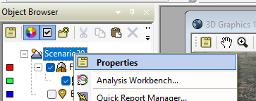
First, we will need to enable Azimuth/Elevation mask analysis on the scenario’s properties page. Right click your scenario in the Object Browser and select Properties.
In the Basic -> Terrain properties of any STK scenario, you will see a few terrain options:
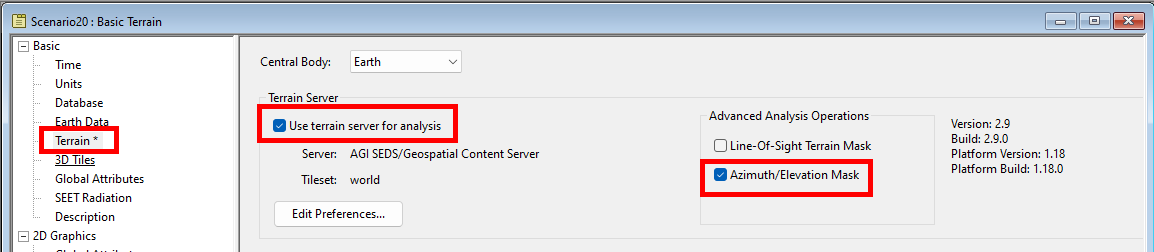
The “Use terrain server for analysis” option must be selected to enable either of the advanced analysis options. Check the Use Terrain Server for analysis checkbox if it is not already enabled and turn on Azimuth/Elevation Mask.
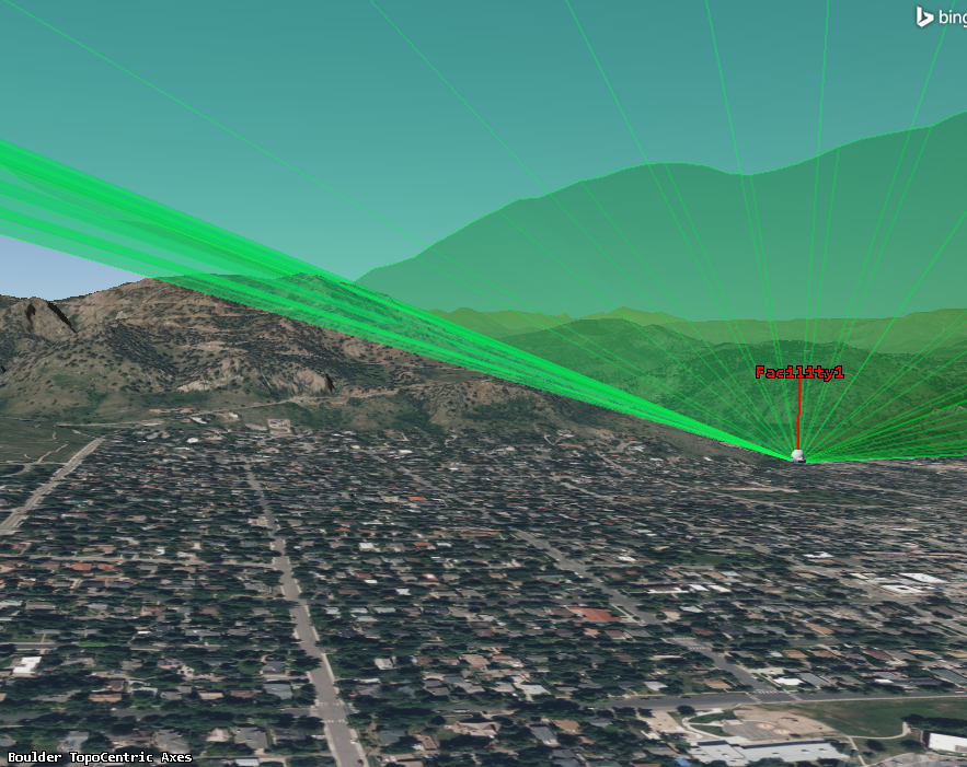
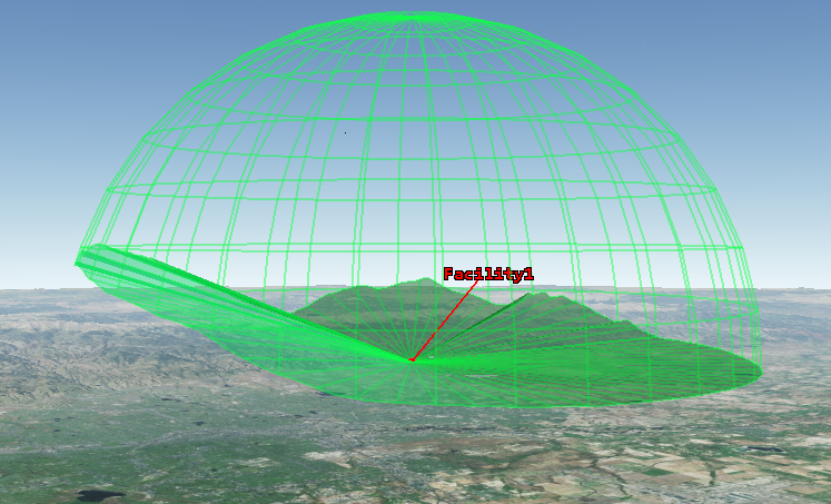
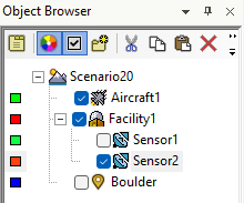
For this example, we have added a facility object near the mountains in Boulder Colorado with a sensor as its child object. The sensor has a simple conic 90-degree field of view that overlaps its surrounding terrain. We will now adjust the sensor’s field of view using a .aem mask file to reflect the constraints of the surrounding terrain.
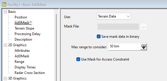
Now that this analysis is enabled, open the properties page of the ground site whose sensor you want to constrain. In this scenario, this would be Facility1. Go to Basic -> AzElMask and set the Use: option to Terrain Data. Enable the “Save mask data in binary” checkbox, as well as the “Use Mask for Access Constraint” and click Apply. STK will now look in all directions around the facility object and determine which directions it has a clear line of sight up to 50 km outwards and save the line-of-sight data as a .aem file for Facility1. Saving the mask data in binary just saves the .aem file as a smaller file.
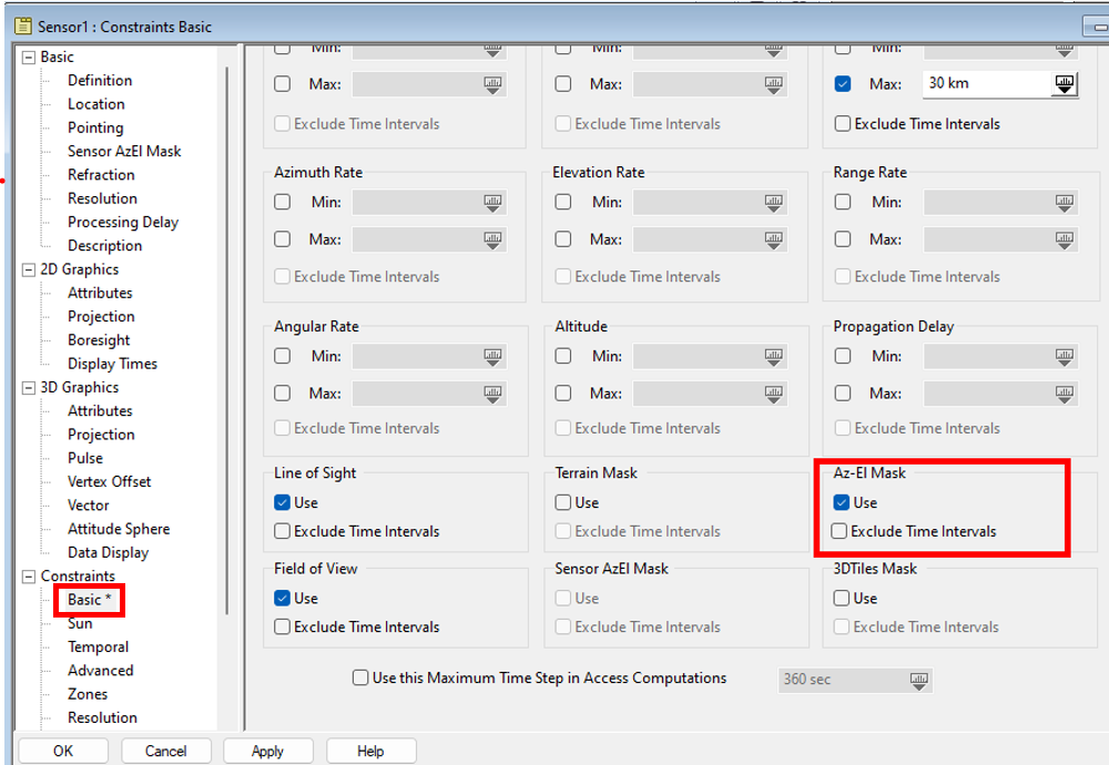
Facility 1 now has the full az-el mask file and will use it in analysis. To enable the attached sensor to use this mask in analysis, right click the attached sensor and open its properties page and navigate to Constraints -> Basic. Enable the Use checkbox under Az-El Mask. This allows the sensor to inherit the field of view constraints of the Facility.
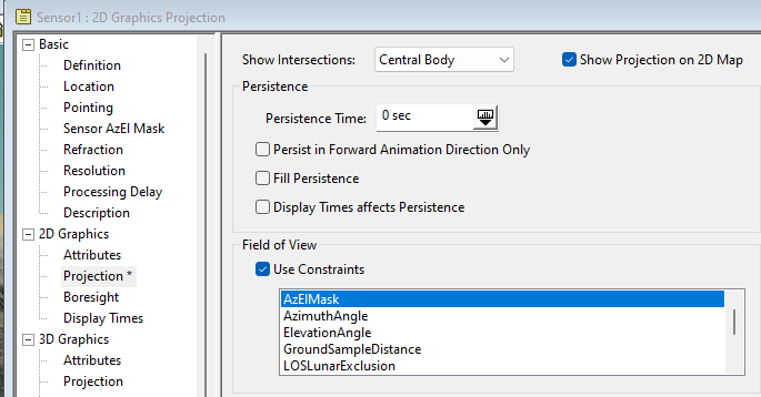
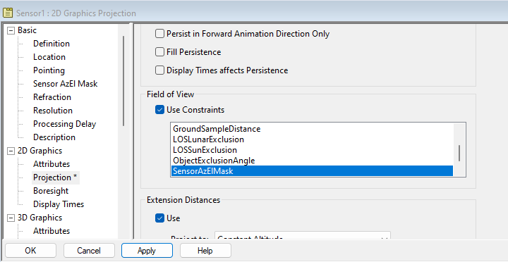
To visualize this mask constraint, go to 2D Graphics -> Projection and enable the Use Constraints checkbox in the Field of View section. Select the AzElMask option and click apply:
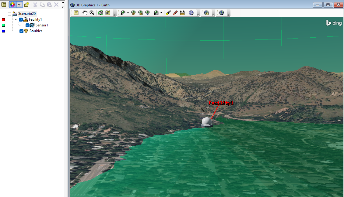
Now your sensor’s true field of view will be shown.
How to Use a Line-of-Sight Terrain Mask:
If you are determining line of sight between two moving objects passing through terrain, or you need an exact measurement with no interpolation, a more accurate but computation intensive option is to regularly recalculate line of sight throughout the scenario’s timeframe with the Line-of-Sight Terrain Mask option. The steps for this are quite similar to the Azimuth-Elevation Mask. First, go to the Basic –> Terrain page for the scenario and switch the advanced analysis option from Azimuth/Elevation Mask to Line-Of-Sight Terrain Mask:

To enable this analysis, you do not need to create the mask file, as this method does not save a static mask. Instead, it computes the terrain constraints of each object’s line of sight (access) throughout the analysis. For comparison, create a new 90-degree field of view simple conic sensor object and attach it to your facility. This sensor does not have the Az-El mask previously computed for Sensor1.
Open the new sensor’s properties page and navigate to Constraints -> Basic. Enable the Use option for Terrain Mask and select Apply. and your sensor will compute the line of sight over the full scenario period for each access that is defined.

Using the Az-El Mask Tool:
As mentioned earlier, the Az-El mask tool is used for constraining line of sight with regard to the 3D models of assets, rather than terrain. It is worth mentioning that this tool creates a .bmsk file that can be connected to your sensor object, while the Azimuth-Elevation Mask used earlier creates a .aem file that is applied to your facility, place or target object. Since each file is applied to a different object, you can use both mask files in conjunction to constrain a line of sight from both considerations.
To illustrate this, we add a facility object in the near field of view to the original facility in a place that will block the line of sight of Sensor1. To use the Az-El Mask tool, right click Sensor1 and select AzEl Mask… from the Sensor subtab.
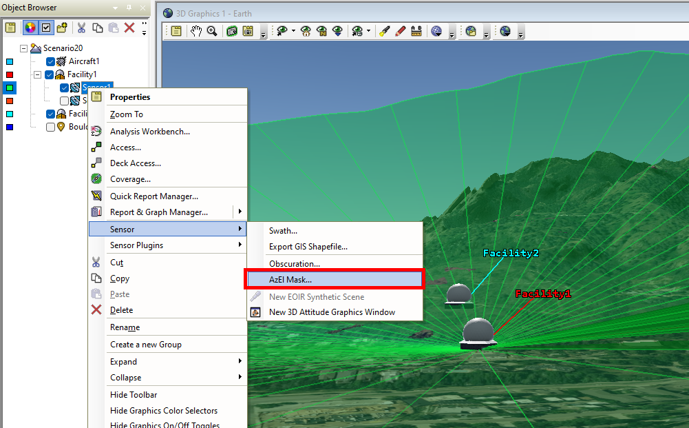
The AzElMask tool will open. Select the object whose line of sight blockage you want to constrain in the “Obscuring Objects” section. In this case, we select Facility2. Set the Window Dim to 800 to ensure a high-resolution rendering, and click Apply, then select Compute. Take note of the name of the .bmsk file.
This will save a .bmsk file to your scenario that includes the field of view blockage of Facility2. To use this in your analysis, open Sensor1’s Properties tab, and navigate to Basic -> Sensor AzElMask. For the Use: option, select Mask File, and use the … button to locate the .bmsk file you saved for the sensor. Select Use Mask for Access Constraint, and click Apply.
Now that this constraint is being used in analysis, you just need to add it to the field of view considerations for visualization. Go to 2D Graphics -> Projection and under Field of View, scroll down and Ctrl+click to select SensorAzElMask (your .bmsk file) and AzElMask (your .aem file). Once they are both highlighted, click Apply.
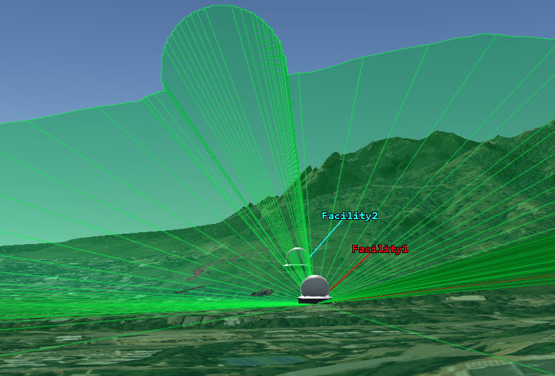
You now can see both the constraints of the terrain and of the 3D models are visualized in your sensor’s field of view.
You have now successfully used STK’s functionality to constrain your objects’ line of sight. This process will allow you to quickly model the constraints of the objects in your scenario and save these constraints for use as you add and remove objects and modify your scenario, as well as how to compute more advanced line of sight in real-time between moving objects in complex terrain.
If you have any further questions or need assistance, we are here to help! Our dedicated Tec-Support team is ready to provide prompt and personalized assistance tailored to your needs. Please don't hesitate to reach out by submitting a ticket by going to https://lsas-tec.freshdesk.com/support/tickets/new. We look forward to assisting you and ensuring a positive experience.
Thanks,
LSAS Tec-Support Team
Was this article helpful?
That’s Great!
Thank you for your feedback
Sorry! We couldn't be helpful
Thank you for your feedback
Feedback sent
We appreciate your effort and will try to fix the article