Planning Satellite Lifetime Fuel Consumption for Stationkeeping Maneuvers with Astrogator
Station-keeping is an essential part of a geostationary asset’s lifetime. As operators try to maintain the space object’s stability in the GEO belt, they have to plan fuel consumption for years to come. Some geostationary satellites are supposed to last for more than a decade. This article will show you how to use Astrogator to plan fuel consumption due to station-keeping operations in the GEO belt.
Properties of Scenario
Start Time: 28 May 2024 15:00:00.000 UTCG
Stop Time: + 1 yr
In this scenario we will study the case of a GEO satellite located above Asia with a starting longitude of 124 degrees, which will suffer from a constant westward drift:
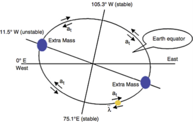
This figure displays the movement of a satellite in GEO. If a satellite is located at 0º longitude, it will drift to the nearest stable point, which is the 75.1º E longitude. Source: [6] H. Li, Geostationary Satellites Collocation. New York: Springer; Beijing, China: National Defense Industry Press, 2014, pp. 124.
Objectives: We will try to maintain a GEO box within 0.1 degrees of difference of East/West longitude, and 0.3 degrees of North/South latitude for a year.
Inserting a reference satellite
We will start by inserting a new satellite object with the Orbit Wizard method.
Make sure to:
- Select the type as geosynchronous and
- Input a subsatellite point value of 124
- Click Ok and Rename the satellite to ”Reference”
Goal: This will be a static satellite which will not be subject to any drift. We will use it to define our centered longitude and define our longitude/latitude box. It is mostly just a starting point reference for our next satellite and also a 3D graphics visualization of our longitude box.
In this satellite’s properties, 3D Graphics – Proximity Page, enter the following values in the Geostationary Box properties:
- Longitude: 124 degrees
- North/South: 0.3 degrees
- East/West: 01. Degrees
- Radius: 42166.3 km
Note: You can disable the orbit track lead and trail 3D graphics in the 3D Graphics – Pass Window by selecting None as the value for more clarity, as well as the label in the 2D Graphics – Attributes page by unticking the Show box.
Create a new TOD Inclination Component
Navigate to the Utilities Dropdown Menu in the top bar of the STK Window and select Component Browser.
In the Show Component Type Dropdown Menu, select Astrogator Components.
Under the Calculation Objects folder, look for Keplerian Elements
Select Inclination and click on the duplicate button.
Rename this new component as “TOD Inclination” by double clicking on its name.
Select the component and click on the properties button.
Click on the Coord. System value and replace the default value by Earth – TOD. This is the True of Date Coordinate System.
Click Ok.
Inserting the Astrogator satellite
Goal: This satellite will operate station-keeping maneuvers whenever certain orbital parameters reach a threshold where the space asset risks getting out-of-station.
Insert a new satellite object using the Define Properties method.
In the Basic - Orbit Page, select the Propagator as Astrogator.
Select the Initial State segment and click on the Initial State Tool… button. In the newly opened window, enter make sure that your parameters match these:
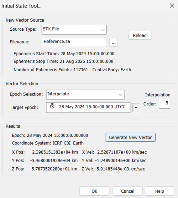
Click Generate New Vector and Ok.
Creating Automatic Sequences
Click on the Automatic Sequences Browser button:
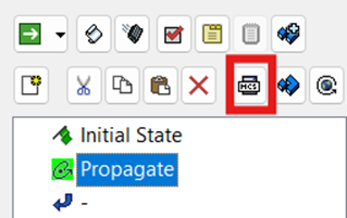
Note: This tool allows you to create full Astrogator Sequences, which means series of Astrogator Segments. You can use these Automatic Sequences to call them in Propagate Segment’s Stopping Conditions, so they are kicking in whenever your spacecraft reaches specific parameters.
Click the New button two times to create two new sequences which will be named WW Station Keeping and NS Station Keeping.
When selecting the WW Station Keeping, click on the Edit button.
Insert the following segments: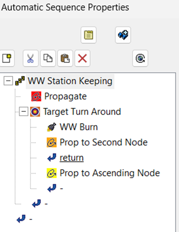
- Sequence: WW Station Keeping
- Contains:
- A Propagate segment with a Periapsis Stopping Condition. Delete the Duration Stopping Condition
- A Target Sequence: Target Turn Around:
- Contains:
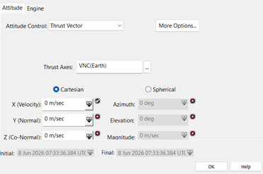
- A Maneuver segment: WW Burn
- Define the Attitude Control as Thrust Vector
- Use VNC (Earth) as the Thrust Axes
- Tick the Target icon in the X field to make it one of your inputs for the differential corrector of the target sequence
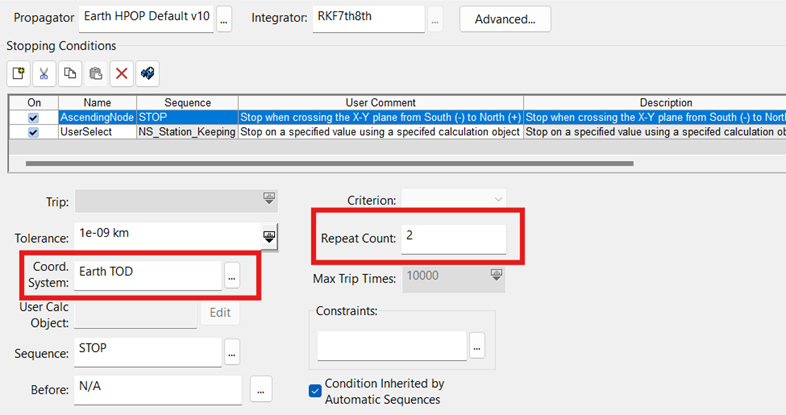
- A Propagate segment: Prop to Second Node:
- Insert a new AscendingNode Stopping Condition with the following parameters:
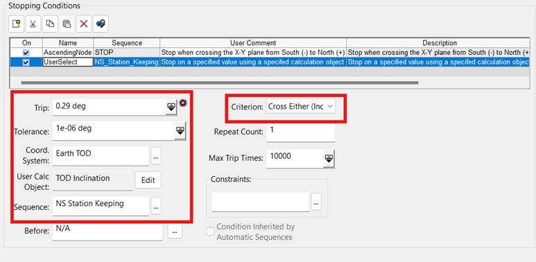
- Insert a new UserSelect Stopping Condition with the following parameters:
- Delete the Duration Stopping Condition
- A Return segment set to Enable (Except Profiles Bypass)
- A Propagate segment with the following properties (Delete the Duration Stopping Condition once you created the AscendingNode Stopping Condition):
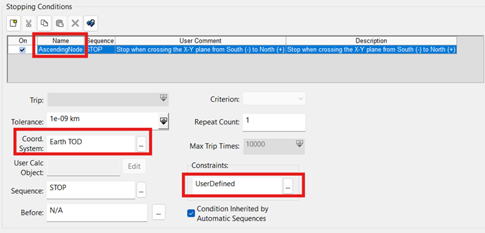
- On the Constraints field, click the ellipsis button
- In the new Select Constraints Window that just opened, select the UserDefined available component and click on the right arrow
- Select the Criteria Value by double clicking on the Criteria row and select Less Than Maximum
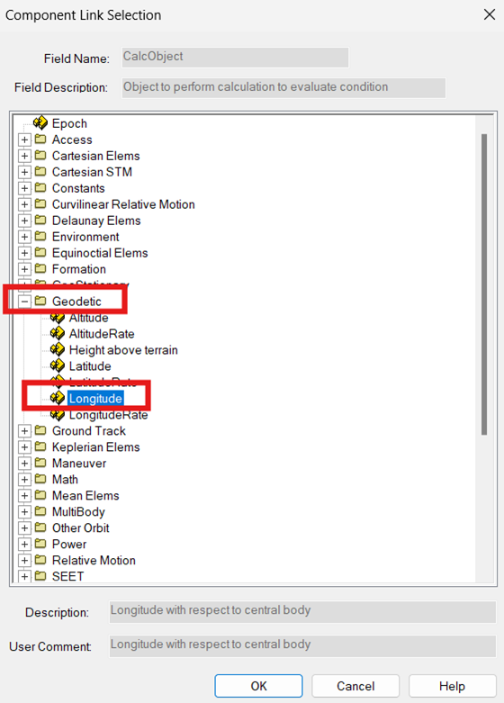
- Repeat this step for the Calc Object value, click Change… button in the Embedded Component Link Window, open the Geodetic folder in the Component Link Selection Window and select Longitude. Click Ok, then click Ok again in the Embedded Component Link Selection Window

- In the Tolerance row, change the value to 0.1 deg
- Your UserDefined constraint parameters should be appearing as such in the Select Constraints Window:
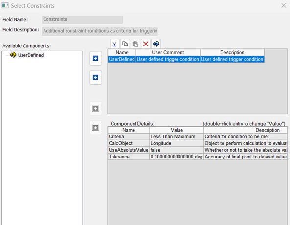
- You can click Ok
- While this Propagate Segment is still selected, click on the Results… button:
- In the Math folder, select Maximum Value and click on the right arrow to add it to the list of results
- Change the Calc Object Value to be the Longitude, located in the Geodetic Folder and click Ok
- In the GeoStationary Folder, select EccentricityX and EccentricityY to input them in the list of results
- Return to the Target Sequence
- Open the properties of the Differential Corrector and set these parameters:
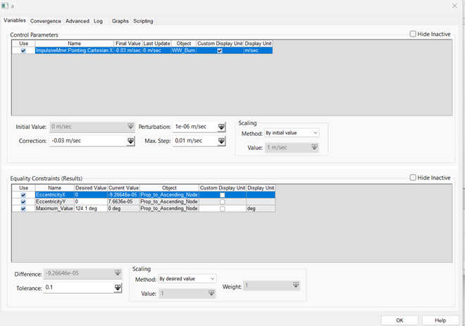
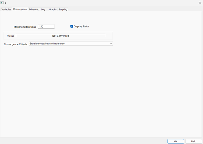
- Click Ok
- Set the Action to Run active profiles
Your Westward Station Keeping Automatic Sequence is ready to get called and kick in. Now let’s create the North/South Station Keeping Automatic Sequence.
- Sequence: NS Station Keeping
- Contains:
- A Target Sequence: NS SK Drift
- Contains:
- A Maneuver Segment: NS Burn :
- As done before, the Attitude Control must be set to Thrust Vector and the Thrust Axes are set to VNC(Earth)
- The X and Y axes are set as control parameters by ticking the target icon
- In the Engine tab, next to the Attitude Control tab, tick the Apply
- Make sure that the NS Burn segment is still selected, and click on the Results… button
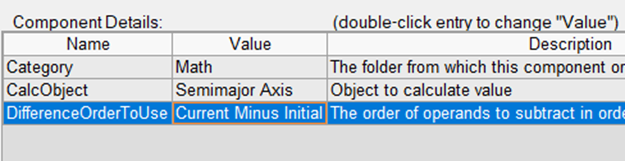
- In the Math Folder, select the Difference component:
- Change the CalcObject Value by double click on it and selecting Semimajor Axis under the Keplerian Elems Folder
- Change the DifferenceOrderToUse Value to Current Minus Initial
- In the Keplerian Elems Folder, select the custom TOD Inclination component and input it in the list of results
- In the GeoStationary Folder, select EccentricityX and EccentricityY and make sure they are in the list of results
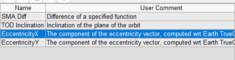
- Click Ok
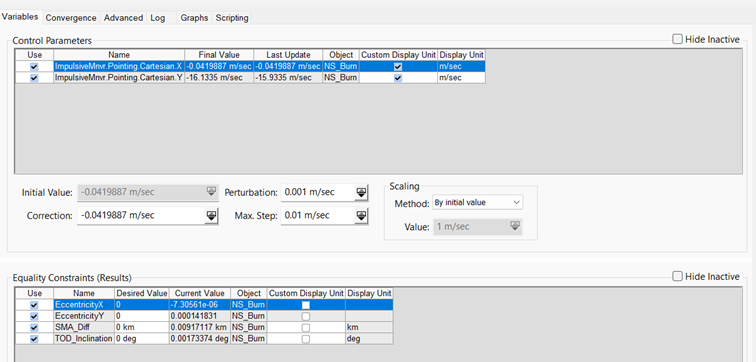
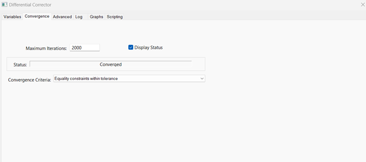
- Return to the Target Sequence to configure it:
- In the Differential Corrector properties, set the parameters as such:
- Set the Action to Run active profiles
- Close the Automatic Sequence Menu
Your North/South Station Keeping Automatic Sequence is ready to get called and kicked in.
Defining the conditions triggering the automatic sequences
- Navigate to the Propagate Segment of your Astrogator’s satellite MCS.
- Add three different Stopping Conditions:
- Periapsis, which you will name Periapsis WW
- AscendingNode, which you will name AscendingNode NS
- Duration
- Configure the Periapsis WW Stopping Condition:
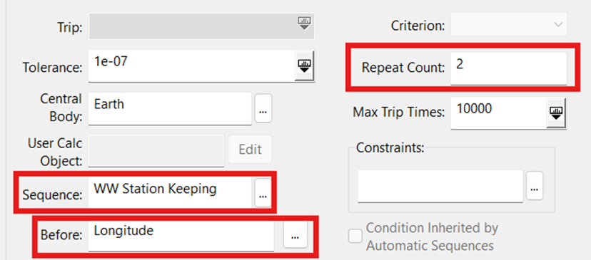
- To create the Before setting, click on the ellipsis button
- In the Stop Before Window, click the New button
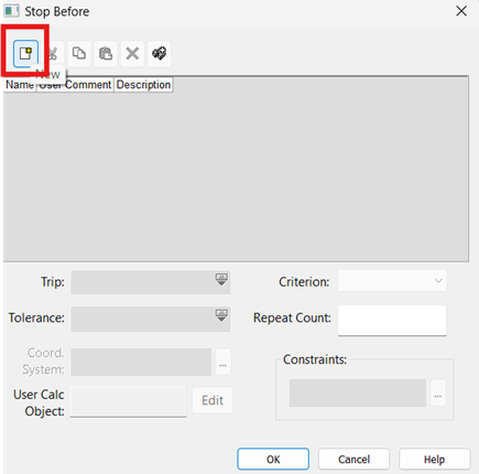
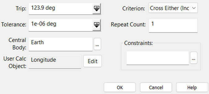
- Select Longitude as the Stopping Condition and click Ok
- Enter the following parameters and click Ok:
- Configure the AscendingNode NS Stopping Condition:
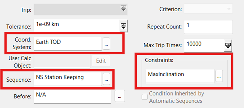
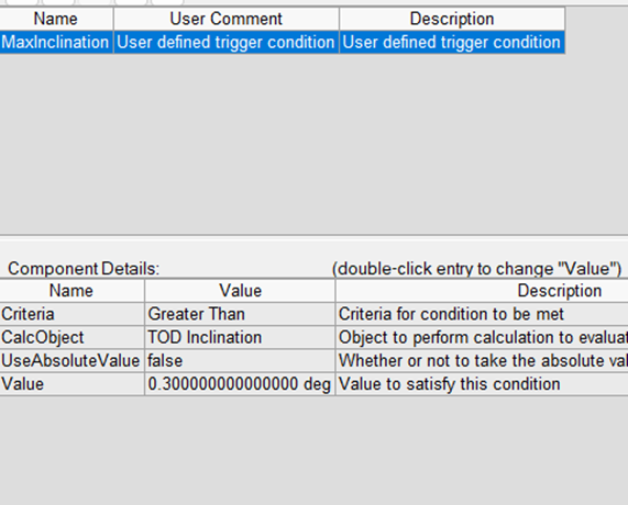
- To configure the Constraints MaxInclination, click the ellipsis button
- Select the UserDefined available component, and rename it MaxInclination
- Make sure the Criteria Value field is set to Greater Than
- Change the CalcObject Value field to TOD Inclination, located in the Keplerian Elems Folder
- Modify the Value to match 0.3 deg
- Configure the Duration Stopping Condition:
- Change the Trip Value to 1 yr
Running the MCS
This MCS will run for a year, so it might take a long time for you to compute all of the target sequences. You might end up with a DID NOT CONVERGE message on the top of the target sequence convergence progress window, but that may be related only to the duration stopping condition triggering after one year. The actual trajectory for a year should be fine.
Once complete, you can clean up the 3D graphics by clicking on the  Clear Graphics button.
If you animate the scene while watching the 3D Graphics Window, you should see your satellite maneuvering over time to avoid getting out of its geostationary box!
Analyzing results: fuel consumption
- Right-click on your satellite object in the Object Browser and select Report & Graph Manager
- In the Installed Styles Folder, generate the Maneuver Summary Report
- You should see all of the maneuvers with their detailed information and a summary at the bottom of the page establishing the totals for delta-v and fuel consumption over the fuel year of station keeping!
Conclusion
Our satellite needed a yearly delta-v of 50.38 m/s to stay in a longitude box of 0.1 degrees of difference and latitude box of 0.3 degrees of difference. This type of number is extremely realistic given that most GEO satellites are designed to use around 50m/s delta-v per year for station keeping.
In this scenario, we used a more advanced design of Astrogator target sequence to evaluate the yearly consumption of fuel and the total delta-v necessary for a GEO satellite constrained by a westward drift. We saw that STK Astrogator can accurately compute these parameters, as well as automatically trigger sequences meeting our expectations.
If you have any further questions or need assistance, we are here to help! Our dedicated Tec-Support team is ready to provide prompt and personalized assistance tailored to your needs. Please don't hesitate to reach out by submitting a ticket by going to https://lsas-tec.freshdesk.com/support/tickets/new. We look forward to assisting you and ensuring a positive experience.
Thanks,
LSAS Tec-Support Team
Was this article helpful?
That’s Great!
Thank you for your feedback
Sorry! We couldn't be helpful
Thank you for your feedback
Feedback sent
We appreciate your effort and will try to fix the article