
Modeling Airspace Violations for Enhanced Air Defense Capabilities with STK
An airspace violation occurs when an aircraft enters controlled or restricted airspace without proper authorization or deviates from its assigned flight path. These incidents are typically the result of navigational errors, communication misunderstandings, or lack of awareness about airspace restrictions. In this article, we delve into modeling airspace violations in conjunction with ground radar systems. This will allow you to model all types of airspace violations.
Using Area Target Objects as Airspace Borders
The Area Target object models a region on the surface of the central body. You can use the Boundary constraint to add several geographic points defined by their latitude and longitude after selecting the Area Type called "Pattern". You can simply add points by clicking on the 2D map after having opened the Area Target's Boundary properties and you can see the results below:
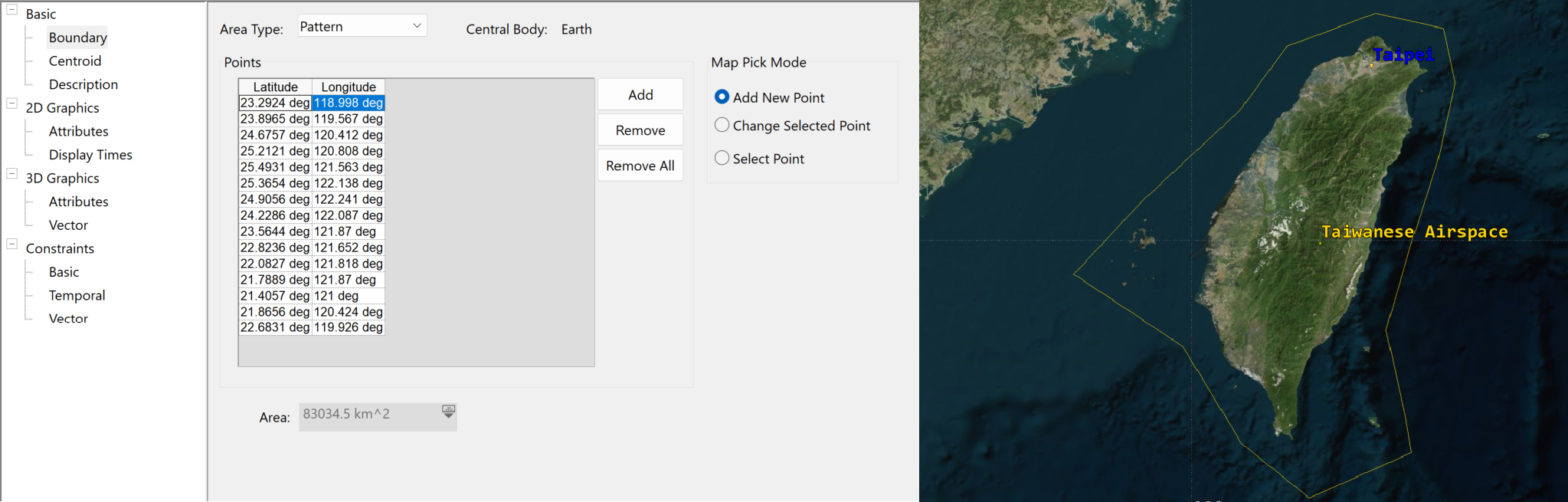
Regarding the Centroid position, it can be automatically computed by STK after setting your Boundaries positions.
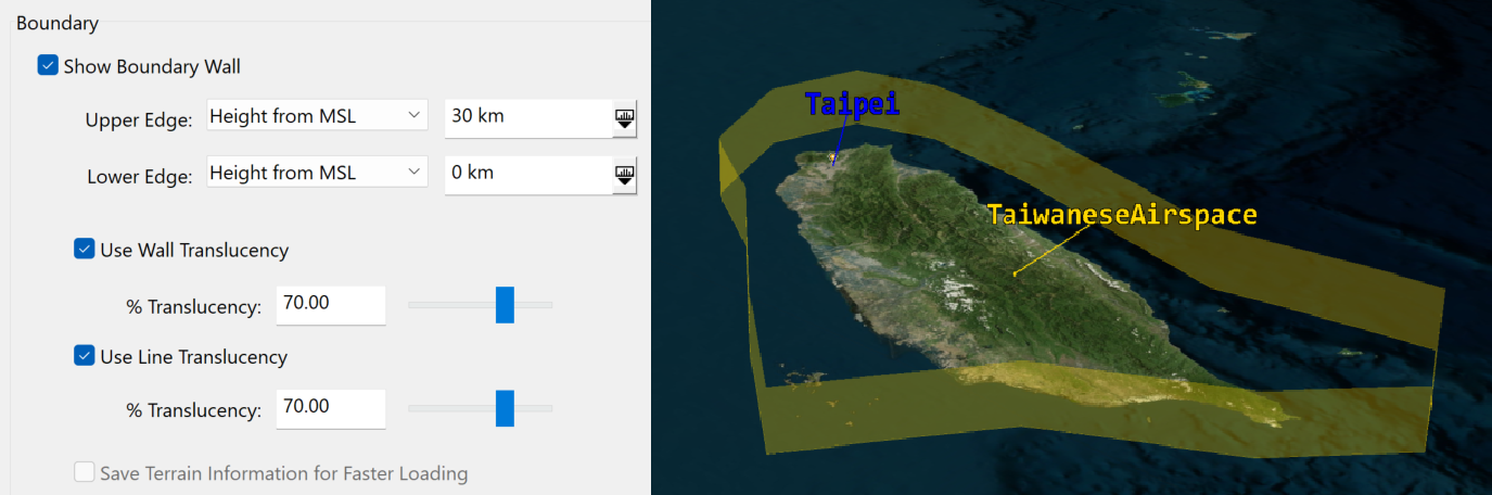
For 3D visualization purposes it is interesting and visually pleasant adjust settings in your 3D Attributes Page - Attributes. You can check the Show Boundary Wall option and for example set up a 30km Upper Edge and 0km Lower Edge using Height from MSL as reference since our airspace boundaries positions are set on the sea. You can also adjust Wall Translucency and Line Translucency as you wish:
Finally, the last step is to set up your Constraints Page - Basic. If you simply want to verify the moments where the incoming aircraft crosses the airspace wall and how long it stays within the airspace until it crosses it back out, you will have to adjust the Minimum Elevation angle to 90 degrees.
The Minimum Elevation angle specifies the minimum elevation angle between the relative position vector from a point within or along the area target or line target to the object of interest and the local horizontal plane at the point within or along the area target or line target.
Make sure that your Line of Sight constraint is also selected. You Area Target Object is now configured!
Modelling a ground spinning sensor
Depending on the types of radar systems you would like to use, you may have different types of sensors to set up in STK. Here we will use a simple dome radar in Taipei, and we will see it spinning within the volume that it can cover.
First, we set up a Facility Object named "Radar", located in Taipei (we used the Geodetic coordinates from the Taipei Place Object which we inserted using the From City Database option).
From there we will attach a first Sensor Object called "Dome" which will represent the global volume covered by our spinning sensor. In the Basic - Definition Page, we will keep the Sensor Type to "Simple Conic" and simply modify the value of the Cone Half Angle to 90 degrees.
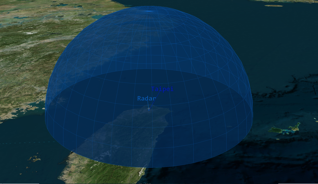
Lastly, we will go to the Constraints - Basic Page and set the Range Max Constraint to 200km. Your dome is all set up and should look like this:
Now let's insert another Sensor Object which we will call "Spinning".
In the Basic - Definition Page, we will set its Sensor Type to "Complex Conic". The following parameters will be entered:
- Half Angles:
- Inner: 0 degrees
- Outer: 90 degrees
- Clock Angles:
- Minimum: 0 degrees
- Maximum: 90 degrees
This will define the shape of your sensor to look like one slice of your dome, just like a pie cake being cut in several slices. This will be the actual volume covered by your spinning sensor at a time in the dome we defined.
Now let's define the Basic - Pointing Page properties so that you sensor can spin 360 degrees around. They should be defined as shown below:
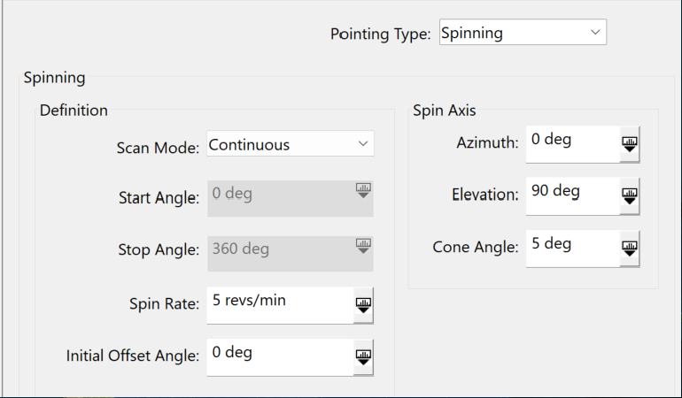
Of course the Spin Rate can be changed depending on your radar performances. The important parameters here are:
- your Scan Mode which allows you to specify whether your sensor should scan from one specific angle to another, be bidirectional or continuous and spin 360 degrees just like in our scenario.
- Your Spin Axis which helps you define around which axis your sensor will be spinning.
Just like the previous sensor, make sure to go to your Constraints - Basic Page and set your Range Max Constraint to 200km.
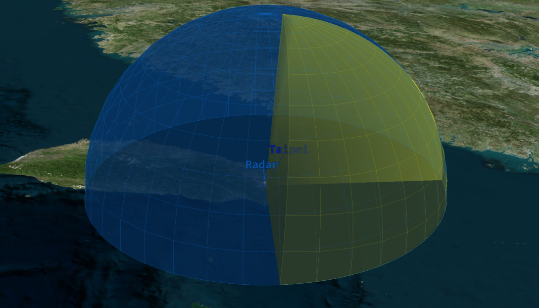
You can see your dome in blue, and your spinning sensor in yellow, taking a slice of your dome area and spinning when playing the animation.
Your sensors are now all set, and if you wish you can attach a Radar object to them! In this scenario we will keep it simple and simply use our sensors.
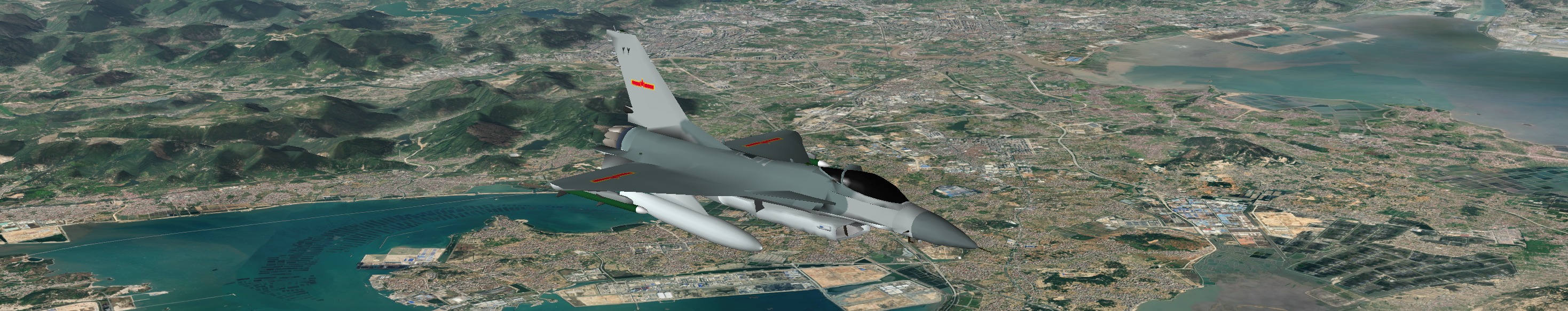
Inserting an airspace intruder
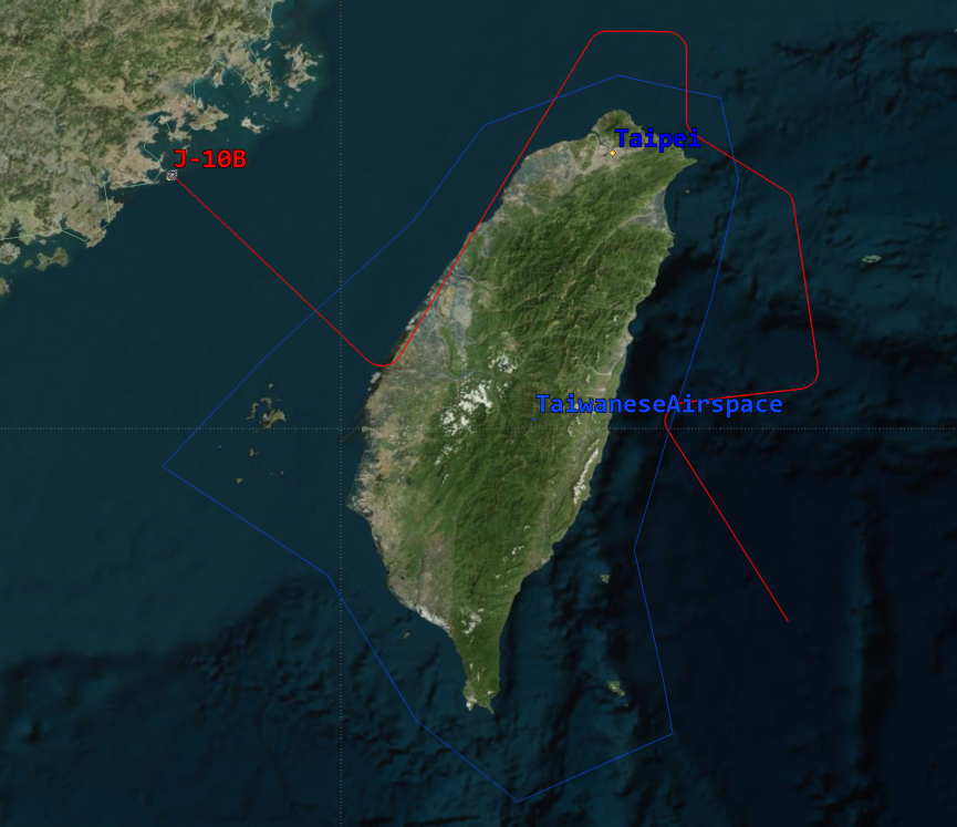
Simply insert a plane and use the propagator of your choice. STK Aviator will be more accurate thanks to its realistic flight path properties and you could also use a realistic flight performance model that matches the real aircraft, but in this case we will use a simple Great Arc Propagator, and just as the we did with the Boundary positions of the Area Target object, we will open the Basic - Route Page and click on the 2D map to select the checkpoints where we want our intruder to proceed and characterize its flight path. Here is our jet fighter flight path, crossing the airspace several times as you can see:
Compute Airspace Accesses
Using the right-click button on our intruder Aircraft object in the Object Browser, we will select the Access button.
Then we will click on the Area Target to highlight it and while holding CTRL, we will click on the spinning Sensor object. Click the Compute button to compute the access between the intruder Aircraft object, the Sensor object and the Area Target object. You can now get different kind of access reports, and most importantly you will directly be able to compare the Airspace accesses to the Sensor accesses and check for performances!
Let's now compare both!
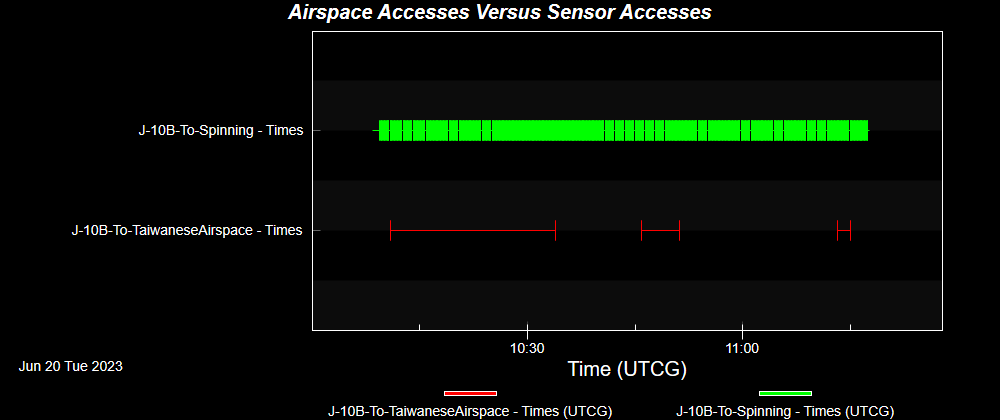
As you can see, our Sensor covers most of the aircraft flight path even when it exits the airspace thanks to its large range and it covers it several times over the length of the scenario because as it is spinning, it loses contact with the aircraft, whereas the Area Target object maintains access during all of the duration of the airspace violation.
For better visualization, you can also go to your intruder Aircraft object - Definition Page and select your 2D Graphics - Attributes Page. There, click Access Interval, then select your Area Target object in the list of Available Objects, and move it to the Selected Object list with the right arrow button.
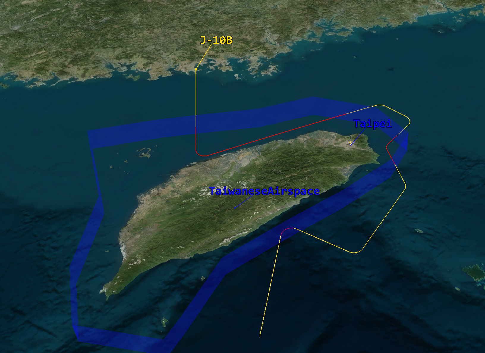
From there, you can see Display Options available. You can make sure to select the Show option for both During Access and No Access Tab, and select the colors of your choice for both. This will allow you to see in the 3D and 2D Graphic windows when your aircraft is within the airspace and when it's not, as shown below (red route when it is in the airspace and yellow when it is not):
As we conclude our exploration of the critical synergy between airspace modeling and ground radar systems, it becomes clear that the ability to simulate airspace violations is indispensable. By employing powerful tools like Systems Tool Kit (STK) to meticulously analyze the performance and access duration of ground sensors when an aircraft enters airspace, we empower our users with invaluable insights.
If you have any further questions or need assistance, we are here to help! Our dedicated Tec-Support team is ready to provide prompt and personalized assistance tailored to your needs. Please don't hesitate to reach out by submitting a ticket by going to https://lsas-tec.freshdesk.com/support/tickets/new. We look forward to assisting you and ensuring a positive experience.
Thanks,
LSAS Tec-Support Team
Was this article helpful?
That’s Great!
Thank you for your feedback
Sorry! We couldn't be helpful
Thank you for your feedback
Feedback sent
We appreciate your effort and will try to fix the article