
STK has a variety of built-in tools for showing articulations and stages on 3D models throughout simulation time. It also has tools for configuring attachment points for sensors and other STK Objects. To do that, it is important to understand how to properly prepare a model for STK.
Resources
-STK 12.10 or newer
-Blender
-Microsoft Visual Studio Code Editor
Model Preparation- Blender
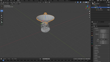
First, you have to select the model you wish to use; in this case, we will be using a free .glb that can be found on NASA’s repository of 3D models for a radar station. Once it’s imported into Blender, its important you join together any small pieces to make articulation and use in STK. This can be done using CTRL+J. This will simplify articulation later on. Keep any components you wish to be able to move independently as their own mesh. Be sure to give them a simple name you will be able to distinguish when editing the code later:
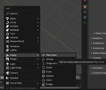
At this stage, I will also give the model any attachment points. SHIFT+A to insert and then choose the empty option like so:
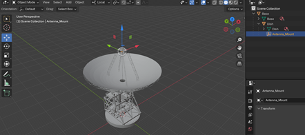
Rename the Empty something like “Sensor_1” or “Antenna_Mount.” Position it where you’d like the attachment point to be on the 3D model. To get it to rotate properly with the dish, I also parented it to the dish’s mesh using CTRL+P and selecting “Object.”
Once you have got the model to the point where you are happy with it, export it as a .gltf:

Model Preparation- Microsoft Visual Studio
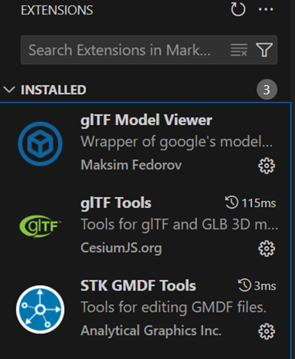
After we have prepared the 3D Model in Blender, we have to modify the code to have the articulations and attach points we want to use in STK. To do this, open Microsoft Visual Studio Code. First, ensure that you have the following extensions installed:
Open your .gltf that you saved from Blender, it should look like this:

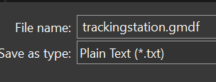
After that, we will create a new .txt file and name it the same as our .gltf, but save it as a .gmdf instead:
Once we have that created, we can add the code to create our articulations and attachment points:
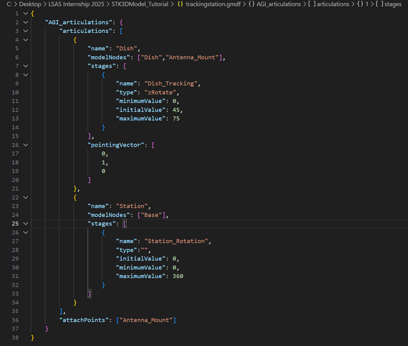
Ensure you have the correct syntax. The “name” fields are up to your discretion. There are several options you can choose from in the “type field”:
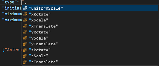
Each has a variety of uses; choose the ones you want to use in STK. For the initial, minimum, and maximum values, you may have to do some trial and error to get them exactly how you want in STK. The same goes for the axis of movement, Blender and STK use different coordinate systems, but STK will articulate about the origin of the mesh defined in Blender, so ensure that it is correct and where you want it to be.
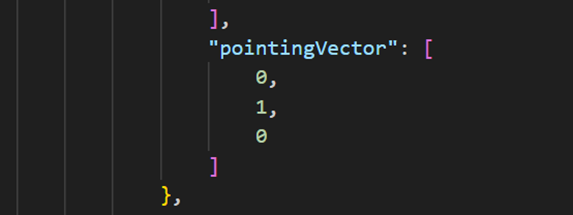
Also, be sure to add the pointing vector so we can make the sensor point in the same direction as the dish is oriented in the 3D Graphics window in STK:
Another key point is formulating the attachment point, as you see at the bottom of this code: 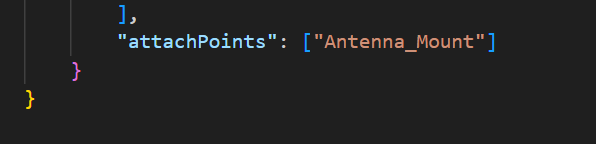
This is a key part to ensure that you are able to mount a sensor or other STK object where you want on the model.
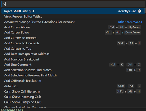
Once you have the articulations and attachment points defined in your .gmdf, you need to transfer them to the .gltf. To do this, open your .gltf file and press F1->Inject .gmdf into .gltf like so:
You should be able to scroll down to each of the nodes in your .gltf and ensure that the .gmdf injection worked properly. If it did, you should see the following:
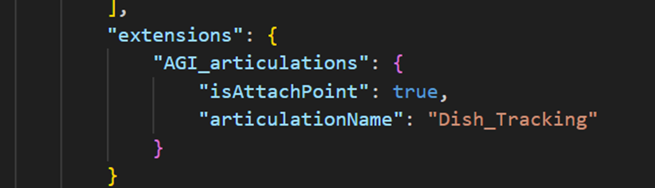
If not, make sure that the .gmdf filename is the same as the .gltf.
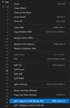
Export the .gltf as a .glb for use in STK:
Bringing your Model into STK
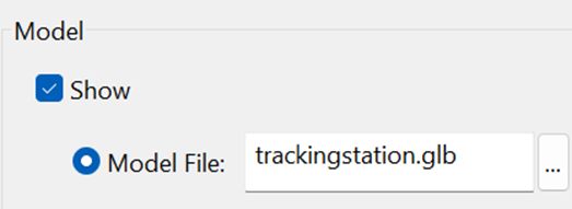
Once you have finished modifying your model file for use in STK, it’s time to check that your articulations and attach points work. Insert your STK object, in this case, a facility. Go to 3D Graphics->Model->Model File: and select your model file you just exported:
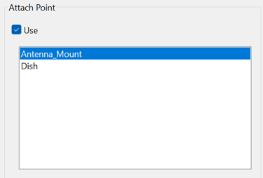
Then go to the 3D-Graphics->Offset page and select Attach Point->Use
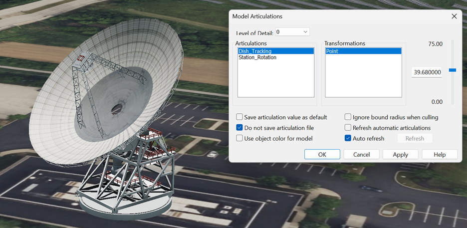
After that, we can view the articulations under the 3D Graphics->Model->Articulations page. Check that these motions make sense with what you had in mind:
After that, we are going to configure the attachment point. To do this, insert a sensor object, with the parent selected as your STK Object, with the model file you just created.
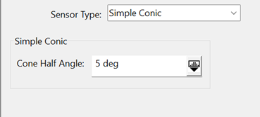
In the Basics->Definitions page, set the cone half angle to 5 degrees to make visualization easier:
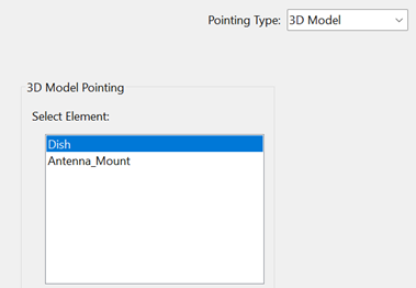
Then go to Basics->Location and select 3D Model from the dropdown menu. Then go to Basics->Pointing and select 3D Model from the dropdown menu. Select the node from the model you wish the sensor to point along, in this case, it’s the dish:
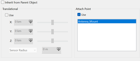
Finally, go to 3D Graphics->Vertex Offset and select Attach Point->Use and select the empty you created in Blender:
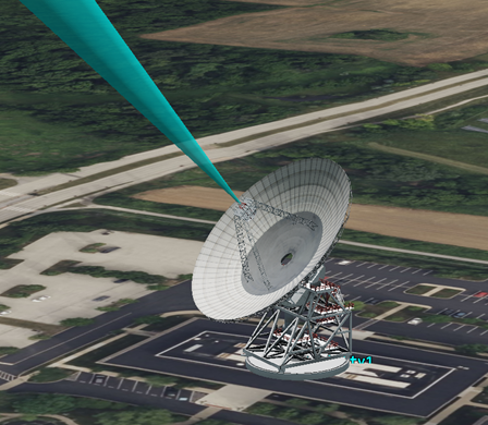
Finally, you can view it in the 3D Graphics window. When you move the articulation of the model, the Sensor should go with it:
Ensure that you are pressing the “Apply” button at the bottom of your articulated STK Object to ensure it will update with the new position.
Next Steps
There are many uses for creating articulations and attachment points in STK that greatly aid in visualization of many key aspects of a scenario. These core skills will work with any STK model you wish to use in the .gltf format.
If you have any further questions or need assistance, we are here to help! Our dedicated Tec-Support team is ready to provide prompt and personalized assistance tailored to your needs. Please don't hesitate to reach out by submitting a ticket by going to https://lsas-tec.freshdesk.com/support/tickets/new. We look forward to assisting you and ensuring a positive experience.
Thanks,
LSAS Tec-Support Team
Was this article helpful?
That’s Great!
Thank you for your feedback
Sorry! We couldn't be helpful
Thank you for your feedback
Feedback sent
We appreciate your effort and will try to fix the article