
This article will discuss how to use STK to model a spinning sensor on fixed or moving platforms. Sensor objects can constrain field of view, line of sight, and other access constraints and provide access metrics. By attaching a radar, transmitter, or receiver as a child object of a sensor, you can connect the child object's performance metrics to the line of sight and access constraints of the spinning sensor, thus modeling an actuated radar, transmitter or receiver. Sensor pointing is therefore the foundation of your radar’s performance analysis.

We will first detail the creation of a sweeping sensor on a stationary facility.
Insert a Place or Facility to which you can attach your sensor. Place and facility icons are represented as such:
![]()
![]()
Their position can be defined with longitude/latitude coordinates, or they can be inserted with the help of the Standard Object Database.
Let's insert Okinawa as a Place.
We will select from the top bar Insert, then New... to open the Insert STK Object dialog:
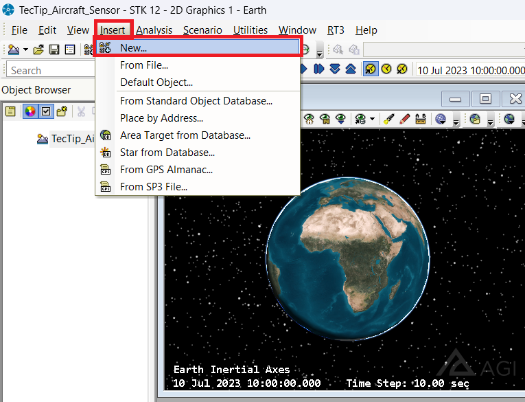
From there, select Place, and for the "Select a Method" parameter, select From City Database and click Insert...

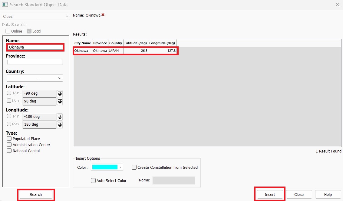
When the Standard Object Database dialog opens, type "Okinawa" in the "Name:" tab. Then click Search. You should see one result. Click this result and click Insert to add the object to the scenario. Close the dialog by clicking Close, but do not close the "Insert STK Object" tool.
Your Okinawa site is now set up on the correct location of the city.
Now, insert your sensor, which is characterized by this icon in STK:
![]()
In the "Insert STK Object" tool, select Sensor, and for the "Select A Method:" parameter, click Insert Default.
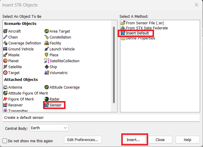
Select Insert, and you will be prompted to select a parent object for your sensor. Select Okinawa as the parent object, click Ok, and close the "Insert STK Object" tool.
Your sensor object is now attached to your place object. The next step is configuring the sensor properties.
Rename you Sensor "Sweeping_Sensor" by right clicking the sensor object in the Object Browser and clicking Rename:
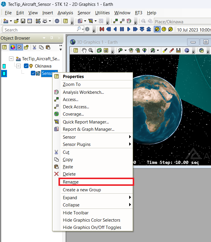
Type in the new name and press enter.
Now right-click the sensor object again and click Properties.
In the Basic - Definition page of Sweeping_Sensor's properties, select Complex Conic for the "Sensor Type:" Then, set the following half angle and clock angle values:
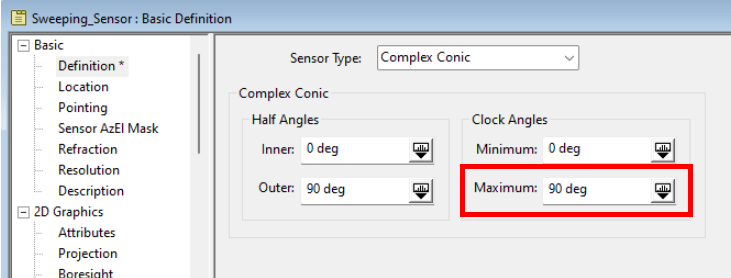
These properties define the sensor's basic field of view. Select Apply.
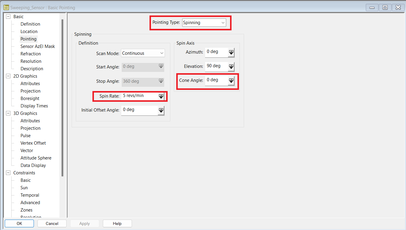
Now go to Basic - Pointing and in the "Pointing Type:" dropdown menu, select Spinning. This will define a spinning sensor's sweep. Set the following properties, and click Apply:
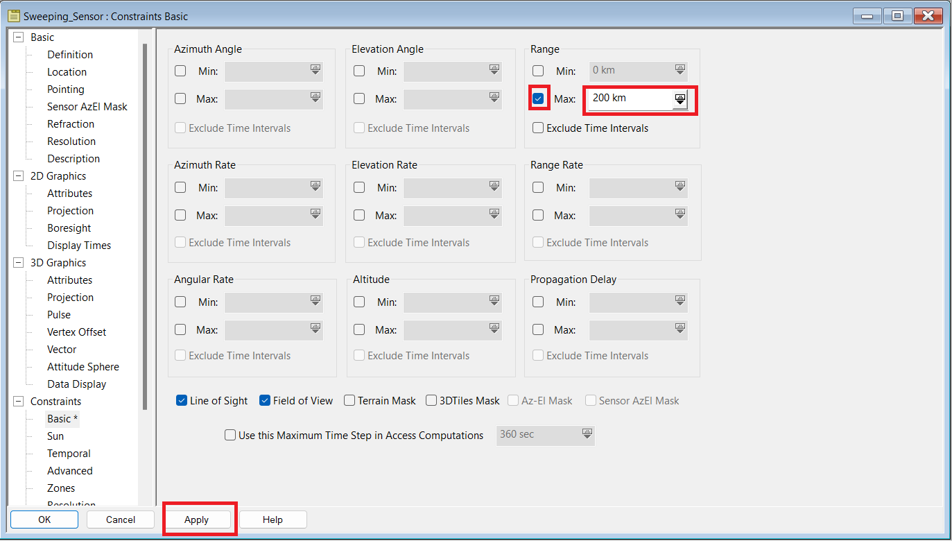
Now that you defined your Sensor's field of view and spinning parameters, you will probably want to constrain it to a certain range. In order to do that, go to Constraints - Basic, input the following values, and click Apply:
Lastly, you want your 2D and 3D projections (visualizations) to match your constraints. In order to do that, go to the 2D Graphics - Projection Tab and look at your "Extension Distance" settings. Set the Use option to checked and select Use Range Constraint in the "Project To:" dropdown menu. Click Apply:
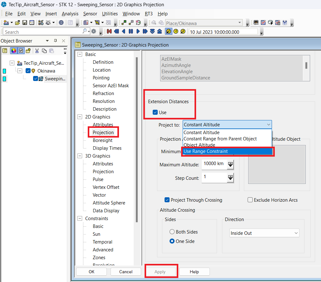
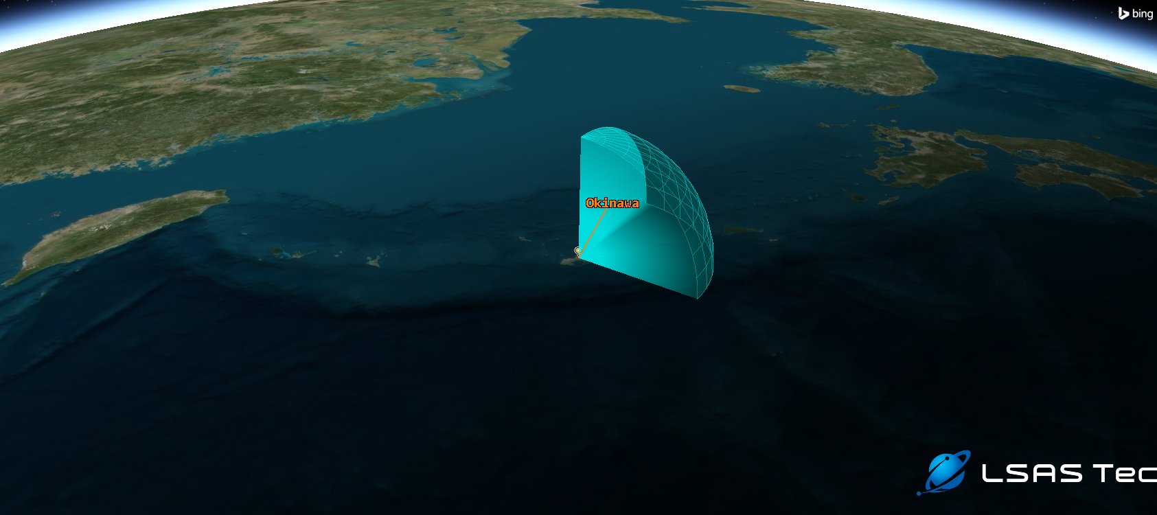
Your static sensor is now spinning! You can attach this type of spinning sensor to any STK object, such as a plane, vehicle or satellite. Additionally, by adding a child object, such as a radar or transmitter, you can generate data metrics for signal transmission, constrained by the field of view and characteristics of the sensor.
Don't forget to save your scenario often!
The Sensor Basic - Definition page allows you to define a Sensor FoV (Field of View) shape with outer and inner half and clock angles. You could have chosen any parameters for this sensor, and the next step of this tutorial will demonstrate attaching a rectangular spinning sensor to a moving aircraft.
A spinning sensor is defined on the Sensor - Pointing page. The Continuous option for "Scan Mode:" models a continuous 360-degree scan. You can simulate a satellite push-broom sensor by using the bidirectional/unidirectional scan modes.
We also demonstrated how to set the number of revolutions per minute our sensor will make, and we changed the Cone Angle, which is the angle between the spin axis and the sensor boresight. As the boresight spins about the spin axis, it maintains an angular distance away from the spin axis specified by this Cone Angle.
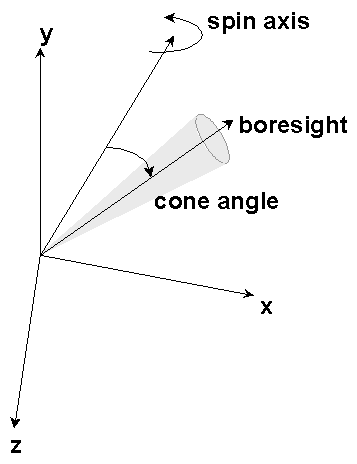
If the cone angle is 0 degrees, the boresight aligns with the spin axis and the sensor looks in one direction all the time but spins about that direction. If the cone angle is 90 degrees, the boresight spins about in a plane perpendicular to the spin axis, typical when creating a sweeping or scanning sensor.
We will now demonstrate how to configure a sweeping sensor aboard a flying aircraft!
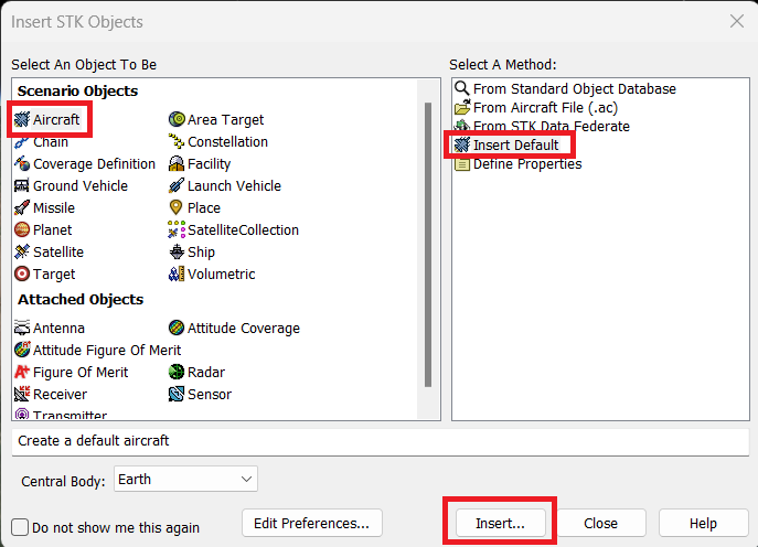
Let's repeat the first steps we went through. Select Insert on the toolbar at the top of your screen and select New to reopen the "Insert STK Objects:" page. Select the Aircraft object, then Insert Default as the method:
Rename your aircraft by right-clicking on your Aircraft Object in the Object Browser on your left side and selecting Rename. Type "EW_Aircraft" and press Enter.
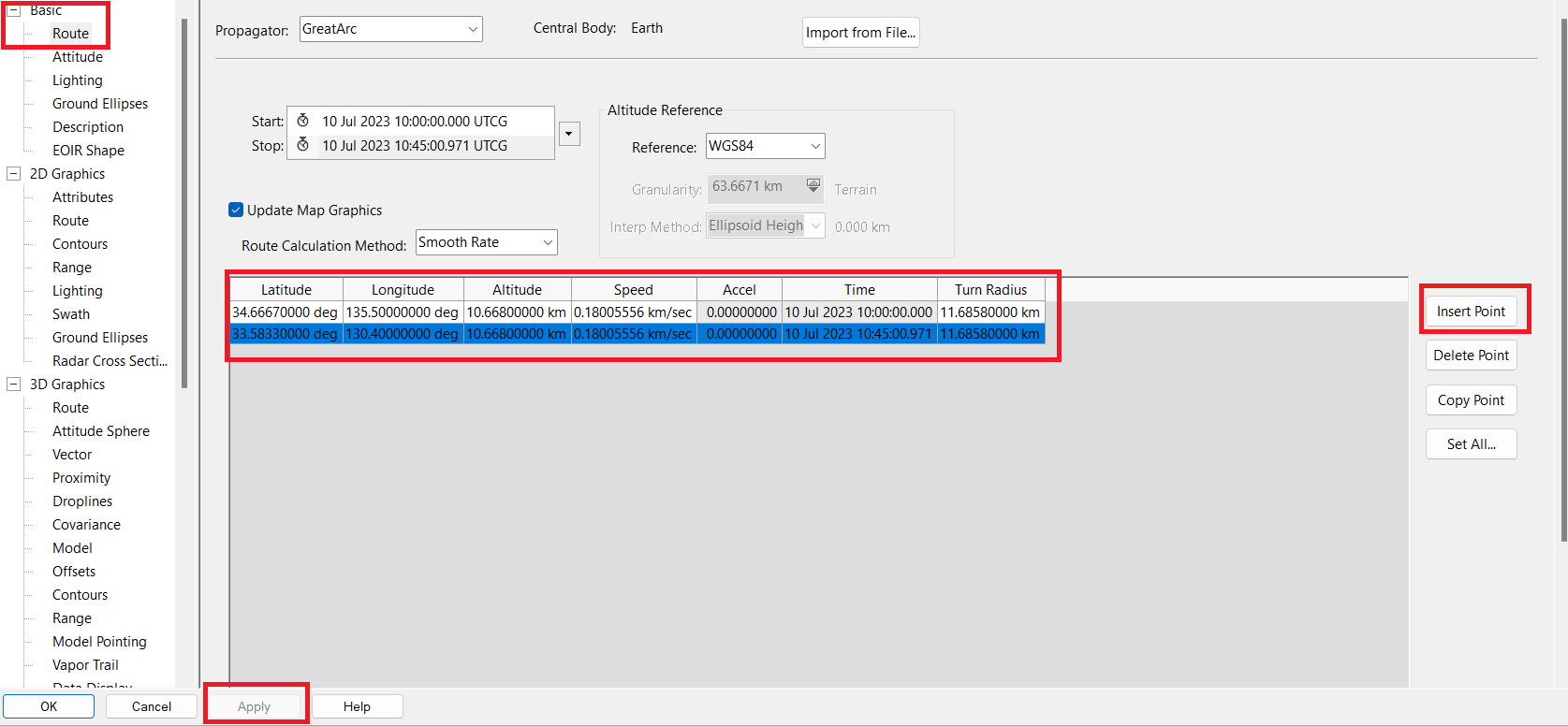
Right-click again on your EW_Aircraft and click on Properties. You will now create a new trajectory from Osaka to Fukuoka. Stay in the Basic - Route tab. Make sure that the "Propagator:" selected is GreatArc, and click Insert Point twice to add two checkpoints.
Enter the following latitude/longitude values in your points, and click Apply:
Latitude | Longitude |
34.66670000 deg | 135.50000000 deg |
33.58330000 deg | 130.40000000 deg |
Your screen should look like this now:
Now that you set up your platform's trajectory, you can set up your sweeping sensor.
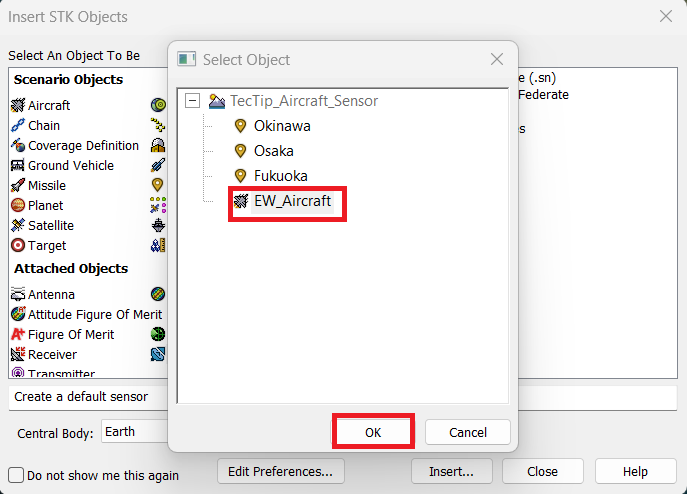
In the same fashion as before, insert a new Sensor Object with the Insert Default method and when prompted by the Select Object dialog, select the Aircraft as a parent object for the sensor:
As before, rename the sensor "Airbone_Sweep" by right-clicking it and selecting Rename.
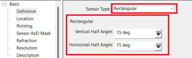
Right-click again and select Properties. In the Basic - Definition page, select Rectangular in the "Sensor Type:" dropdown menu. Set both half-angle values to 15 degrees:
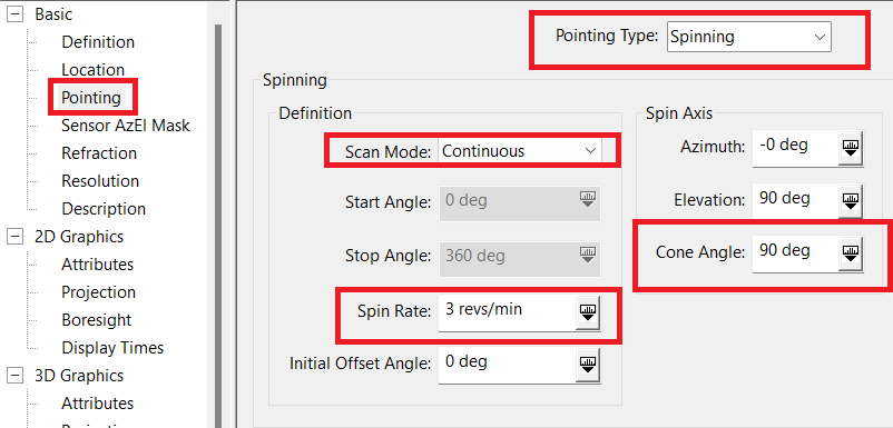
The geometry of the sensor is changed by the fact that the aircraft is a flying platform and not static on the ground. Thus, we will change the cone angle value to 90 degrees instead of the 0 we had before. We will also lower the number of revolutions per minute to a more realistic value for a rotodome.
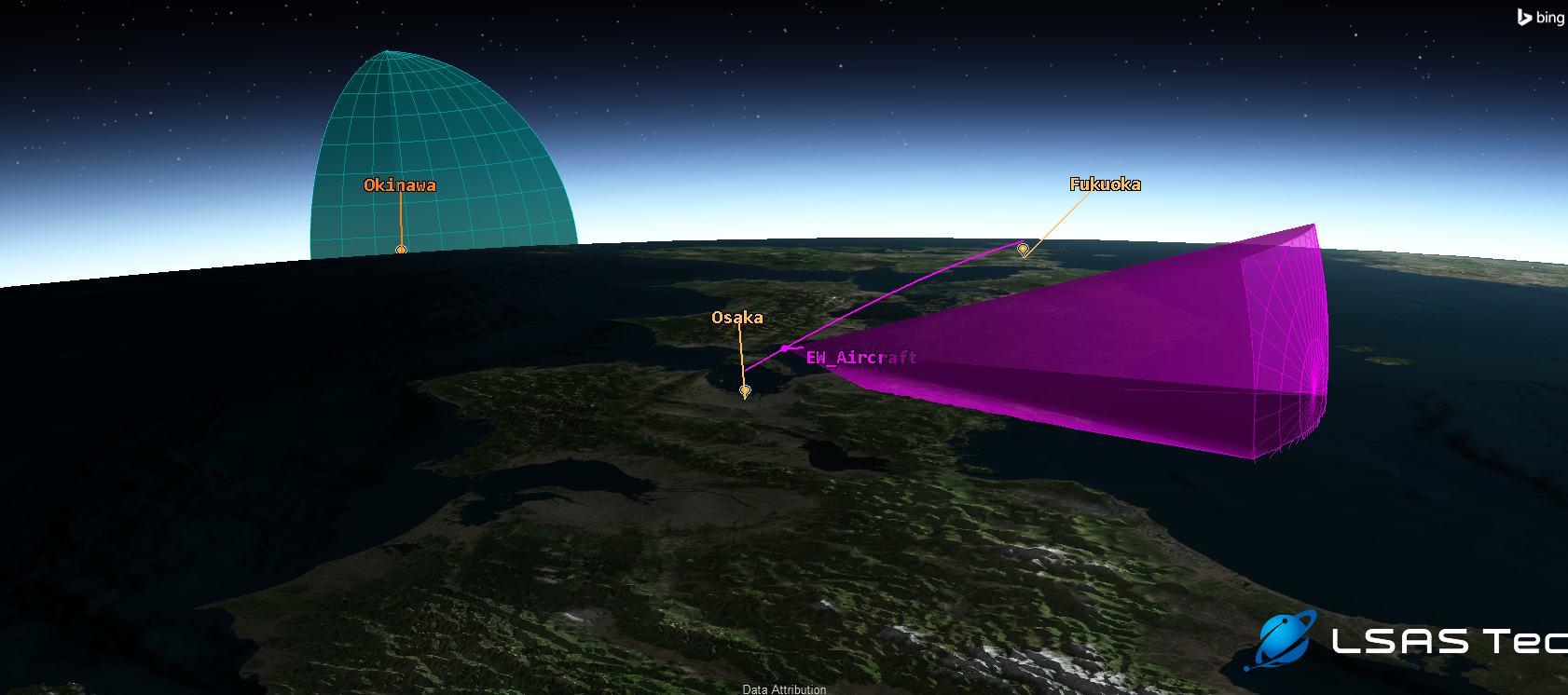
See below the spin axis visualized as a vector:

Finally, set a maximum range constraint in the Constraints - Basic page and configure your 2D Graphics - Projection options to use extensions and set the "Project To:" value to Use Range Constraint.
You can now admire your spinning radar mounted on your aircraft! Remember to save your scenario!
If you have any further questions or need assistance, we are here to help! Our dedicated Tec-Support team is ready to provide prompt and personalized assistance tailored to your needs. Please don't hesitate to reach out by submitting a ticket by going to https://lsas-tec.freshdesk.com/support/tickets/new. We look forward to assisting you and ensuring a positive experience.
Thanks,
LSAS Tec-Support Team
Was this article helpful?
That’s Great!
Thank you for your feedback
Sorry! We couldn't be helpful
Thank you for your feedback
Feedback sent
We appreciate your effort and will try to fix the article